Automatic Return Tank Water-Level Control Assembly

$330.00

Shipping and applicable taxes are additional.

Automatically control boiler return tank water levels with electronic sensing and automatic valve control. The G&A Engineering Automatic Return Tank Water-Level Control Assembly replaces a conventional mechanical ball-float valve with an external electronic water-level sensor, control unit, and water-supply solenoid valve. Key points:

  • Electronic water-level sensing
  • Automatic water-supply control
  • Sensor mounts outside the sight glass
  • No conventional mechanical float required
  • Manual override available
  • Designed for boiler return tanks and condensate return systems
- +

The Problem

Conventional boiler return tanks generally use a mechanical ball-float valve to regulate incoming water.

The operating principle is simple. When the water level drops, the float falls and mechanically opens the valve to admit water. As the tank fills, the float rises and closes the valve.

The problem is that mechanical float valves can wear out, stick, or fail to seal completely over time. When this happens, water may continue entering the tank even after it reaches the proper level.

This can lead to the following problems:

  • Unnecessary water use
  • Excessively high water levels in the return tank
  • Tank overflow
  • Increased pressure in the condensate return system
  • Water hammer, vibration, and possible damage to piping or equipment
  • Additional maintenance and service costs

G&A Engineering developed a more modern alternative to address these problems with the conventional approach.

A Better Way to Control Return Tank Water Levels

The G&A Engineering Automatic Return Tank Water-Level Control Assembly replaces the conventional mechanical float-valve approach with electronic water-level sensing and automatic valve control.

Instead of installing a mechanical float inside the tank, the system detects the water level through the tank’s existing sight glass.

When the water reaches the set level, the electronic sensor sends a signal to the control system, which automatically operates the water-supply solenoid valve.

In simple terms:

  • The sensor detects the water level.
  • The controller determines whether action is needed.
  • The solenoid valve controls the water supply.

This eliminates the need for a conventional mechanical float moving up and down inside the return tank.

How It Works

01

Electronic sensor detects the water level

The electronic water-level sensor is mounted on the outside of the return tank’s sight glass.
The installer positions the sensor at the desired operating level and adjusts it to detect water accurately when it reaches that point.
Because the sensor is mounted outside the sight glass, no water-level sensing device needs to be placed inside the tank.

02

Control unit receives the sensor signal

The electronic sensor is connected to the control unit.
As the water level changes, the system determines whether additional water is needed.

03

Solenoid valve controls the water supply

The control unit operates an electric water-supply solenoid valve.
When additional water is needed, the valve opens to supply water to the return tank.
When the set level is reached, the system closes the valve.
The result is automatic return tank water-level control without relying on a conventional mechanical ball-float valve.

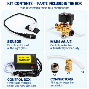
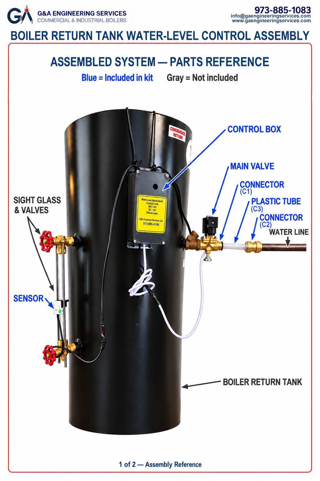
Three Main Components

The system consists of three main components.

Electronic Water Level Sensor

Mounted outside the sight glass to detect the set water level.

Control Unit

Receives signals from the sensor and controls operation of the water-supply valve.

Water Supply Solenoid Valve

Opens and closes automatically in response to the control system to regulate the water supply.

The supplied solenoid valve also includes a manual override, allowing water to be supplied manually when needed, independently of automatic control.

Why Replace a Conventional Ball Float Valve

Mechanical float valves have been used for many years because of their simple design.

However, they rely on moving mechanical parts and a mechanical seal to regulate the water supply.

The G&A system performs the same function in a different way.

Conventional Ball Float Valve
  • Mechanical operation
  • Float located inside the tank or at the tank side
  • Moving mechanical parts regulate the water supply
  • Valve may fail to close completely as it wears
  • Water may continue entering if the valve does not close properly
G&A Automatic Water Level Control Assembly
  • Electronic water-level sensing
  • Sensor mounted outside the sight glass
  • Electrically controlled automatic water supply
  • No mechanical float required inside the tank
  • Main control components located outside the return tank
  • Indicator light makes sensor operation easy to check
  • Manual operation of the solenoid valve available when needed

The system consists of three main components.

A small leak through a float valve may initially seem like a minor maintenance issue. But if water continues entering the return tank unnoticed, it can lead to larger problems.

Reduce Unnecessary Water Use

The system automatically shuts off the water supply when the set level is reached.

Help Prevent Return Tank Overflow

Electronic water-level sensing helps maintain the desired operating level instead of relying solely on a mechanical float valve to close properly.

Protect the Condensate Return System

Excessively high tank water levels can create undesirable operating conditions in the condensate return system.
Maintaining the proper level helps the system operate reliably as designed.

Reduce Dependence on Mechanical Float Components

With the water-level sensor and controls installed outside the tank, the system controls the water level without a conventional mechanical float assembly inside the tank.

Simplify Inspection and Maintenance

Because the main control components are external, technicians can visually check, inspect, and service the system without relying on an internal tank float assembly.

From an 18th Century Principle to a 21st Century Solution

The basic principle of the mechanical float valve has been used for hundreds of years.
Although this approach remains useful in many applications, today’s boiler systems do not have to rely solely on mechanical floats to control return tank water levels.
G&A Engineering applies electronic water-level sensing and automatic valve control to this basic water-supply function.

The Old Way
  • Conventional ball-float valve
  • Traditional mechanical water-level control
The Better Way
  • Automatic Return Tank Water-Level Control Assembly 
  • Electronic water-level sensing plus automatic water-supply control

This is the core concept behind the product.

Installation Overview
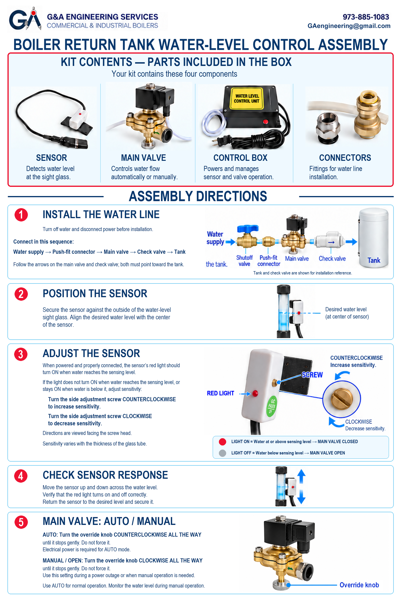
The system is designed for relatively straightforward installation by a qualified technician.

The electronic sensor is installed at the desired water-level position on the return tank’s sight glass.

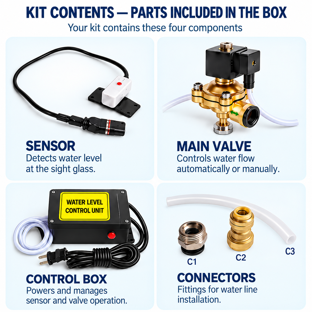
The check valve and solenoid valve must be installed in the water-supply piping in the correct flow direction.

The sensor is adjusted to detect water accurately at the set level. Its indicator light allows the detection status to be checked.

The sensor and control wiring are connected to the solenoid valve.

After setup, sensor and valve operation can be checked by moving the water level above and below the sensor position.

Installation must be performed by a qualified boiler/HVAC technician in accordance with applicable local codes and the manufacturer’s installation instructions.


Manual Override

The supplied solenoid valve has both automatic and manual operating modes. During normal operation, the system controls the valve automatically. When manual operation is needed for service, inspection, or an emergency, the valve can be switched to the manual position to operate the water supply independently of the automatic control system. This also allows separate control of the water supply during inspection or troubleshooting.

Compatible Systems

The G&A Automatic Return Tank Water-Level Control Assembly can be used with:

  • Commercial boiler return tanks
  • Residential boiler systems that use a return tank
  • Condensate return systems
  • Systems equipped with a sight glass for checking the water level

The boiler/HVAC technician responsible for installation must confirm suitability for each specific site.

Warranty
1-year warranty.

What is the return policy?
Returns are accepted within 14 days for a 100% refund or exchange.

What if the product is defective?
The seller pays return shipping for defective items.

Automatic Return Tank Water-Level Control AssemblyAutomatic Return Tank Water-Level Control Assembly
$330.00
- +
Scroll to Top