

G&A Engineering • Return-tank control
Automatic Return Tank Water-Level Control Assembly
Replace the conventional mechanical float-valve approach withelectronic water-level sensing and automatic valve control.
$330
Wholesale available. Contact us for pricing →
Shipping and applicable taxes are additional. Installation by a qualified boiler/HVAC technician.
The problem
When a float valve fails to close.
Conventional boiler return tanks generally use a mechanical ball-float valve to regulate incoming water.
Mechanical float valves can wear out, stick, or fail to seal completely over time. When this happens, water may continue entering the tank even after it reaches the proper level.
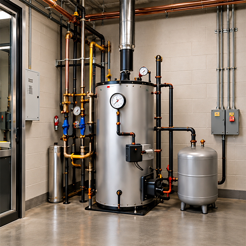
A better way to control return tank water levels
How it works
The system detects the water level through the tank's existing sight glass and automatically operates the water-supply solenoid valve.
01 / SENSOR
Detects the water level
The electronic water-level sensor is mounted on the outside of the return tank's sight glass at the desired operating level.
02 / CONTROLLER
Receives the signal
As the water level changes, the control system determines whether additional water is needed.
03 / SOLENOID VALVE
Controls the water supply
When additional water is needed, the valve opens. When the set level is reached, the system closes the valve.
Sensor detects the level → Controller determines action → Solenoid valve controls the supply
Video Installation Guide
The assembly
Parts included in the box.
The sensor, main valve, control box, and connectors are shown here so you can see the supplied parts before ordering.
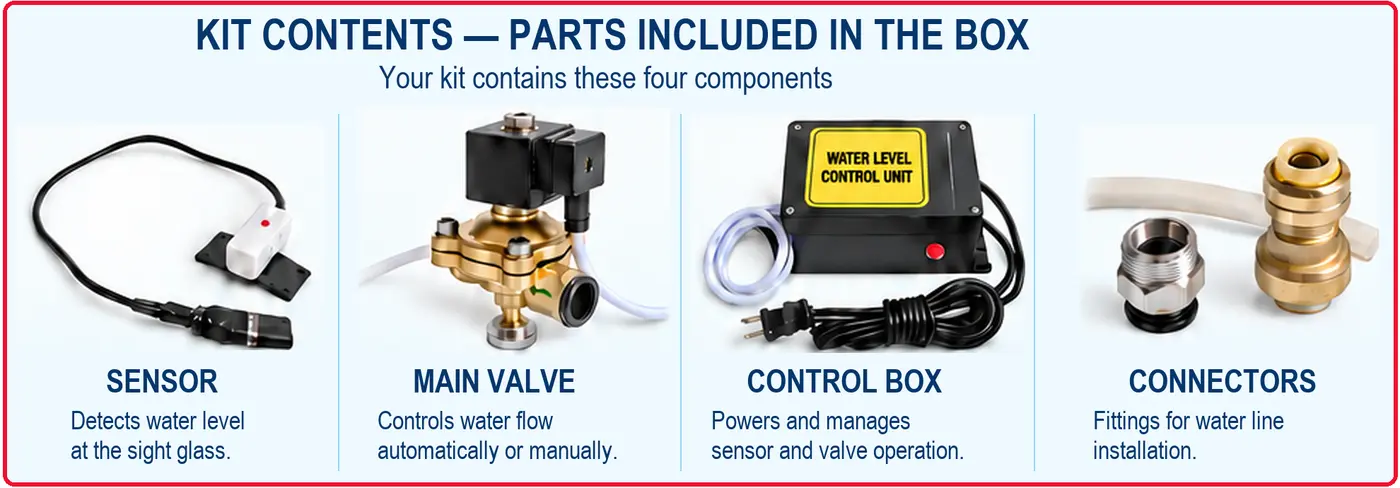
The main valve can control the water supply automatically or manually.
Why replace a conventional ball float valve
The same function, a different way.
Mechanical float valves rely on moving mechanical parts and a mechanical seal. The G&A system performs the same function with electronic sensing and automatic valve control.
The old way
Conventional Ball Float Valve
The electronic water-level sensor is mounted on the outside of the return tank's sight glass at the desired operating level.
The better way
G&A Automatic Water Level Control Assembly
Installation overview
Set the level. Check the operation.
The sensor is installed at the desired water-level position on the return tank's sight glass. The check valve and solenoid valve must be installed in the water-supply piping in the correct flow direction.
After setup, sensor and valve operation can be checked by moving the water level above and below the sensor position.
Installation must be performed by a qualified boiler/HVAC technician in accordance with applicable local codes and the manufacturer's installation instructions.
The better way
G&A Automatic Water Level Control Assembly
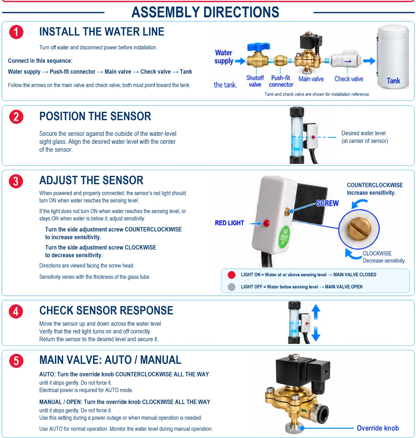
Assembly directions
See the installation steps.
The supplied guide shows the water-line sequence, sensor position and adjustment, response check, and automatic/manual valve operation.
G&A Engineering
Automatic Return Tank Water-Level Control Assembly
Electronic water-level sensing. Automatic water-supply control. No conventional mechanical float required inside the tank.
For installation inquiries, product information, or orders, contact G&A Engineering.
Questions and answers
Does the system require a float inside the tank?
No. The electronic sensor is mounted outside the return tank's existing sight glass.
Can the water supply be operated manually?
Yes. The supplied solenoid valve has both automatic and manual operating modes.
Who should install the assembly?
A qualified boiler/HVAC technician must install it in accordance with applicable local codes and the manufacturer's installation instructions.
How do I check whether it fits my system?
The technician responsible for installation must confirm suitability for each specific site. Call G&A Engineering at 973-885-1083 for product information.